
© John R. Bentley - January 2008.
Installing and using a Stereo Microscope on the Taig Lathe
I haven't discovered or invented anything here that hasn't already been done. Even my choice of this microscope model was strongly influenced from research on the web.
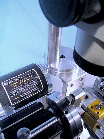
I have taken the concept and applied my own interpretation while installing it on my Taig. I employ a rear-mounted DC motor on my lathe, so designing a custom bracket which would provide proper clearance and strength was one of the requirements in making this instrument suitable for my Taig lathe.
But first things first...
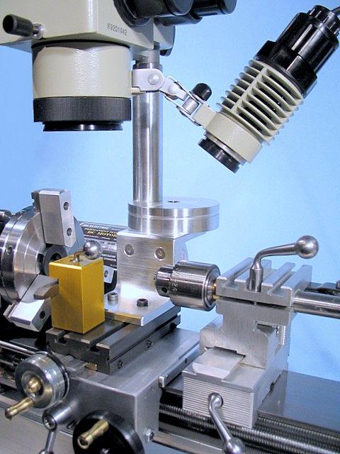
The next consideration in mounting the microscope was to devise a sturdy foot which would attach to the lathe cross slide while providing clearance at the back for the motor and presenting the eyepieces at a comfortable location for easy viewing when operating the lathe.
Perfect balance !
Note below that the mount provides for considerable adjustment. First, the instrument can be revolved on its post for precise location or swung out of the way during setups. The disk can be revolved to set the microscope over the toolbit when the toolpost is mounted in either T-slot. To augment this rotating adjustment, there are tapped holes placed side-by-side in three positions on the angle piece to accept the central screw. In addition the entire bracket can be moved along the T-slots.
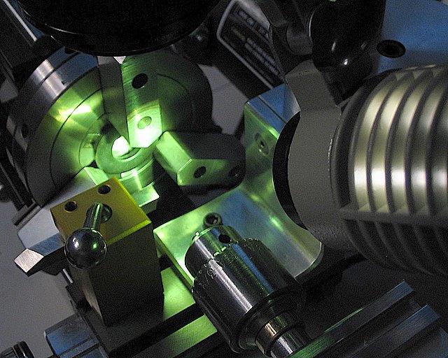
The green light issuing from the MBC-10 illuminator is quite restful and easy on the eyes. It eliminates any tiny rainbow effects (chromatic aberrations) at high contrast locations in the field of view. When working bright metal, these are bound to arise under magnification and eliminating them affords a clearer resolution of the subject. The green filter over the lamp condenser is removable when a true color image is desired for special purposes such as photography.
Illuminator cooling vents and fins are visible on the right
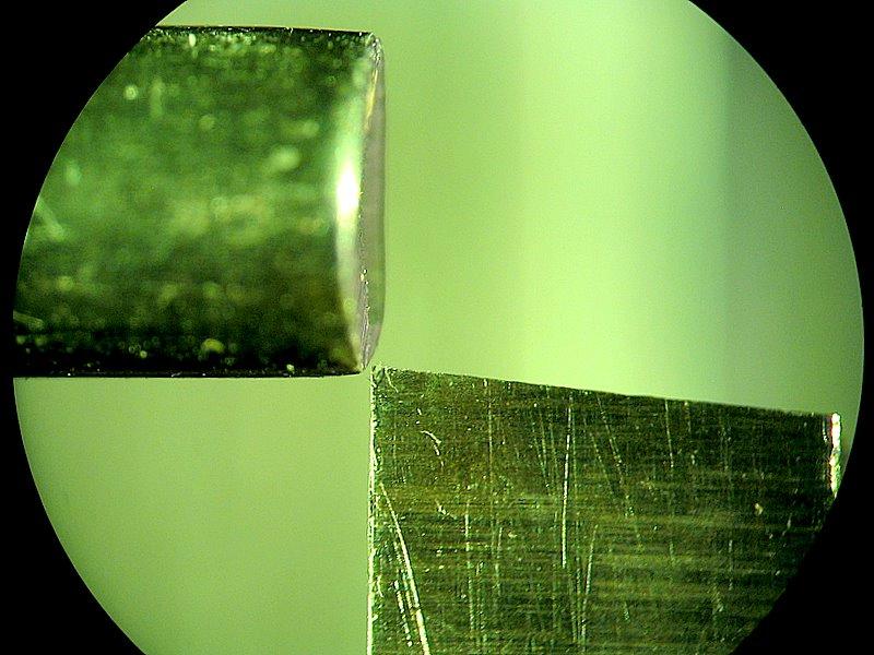
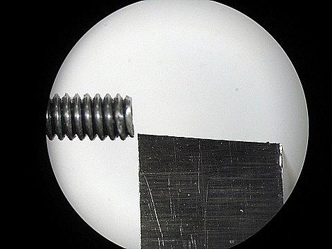
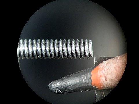
First, they show a 3/16" rod (a Taig chuck tommy bar) and the cutting edge of a 1/4" lathe bit as it protrudes from the toolpost. It is the same bit in both pictures, but note how the scratches show up well in the upper photo, due to a different angle of the near-parallel light source.
An interesting observation:
A quick look at the practicality of using the microscope on the lathe
Bottom right:
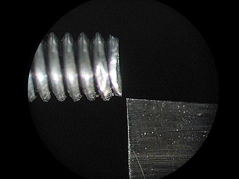
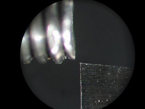
At 58x the depth of field is narrow, only the tool and centerline of the work are in focus.
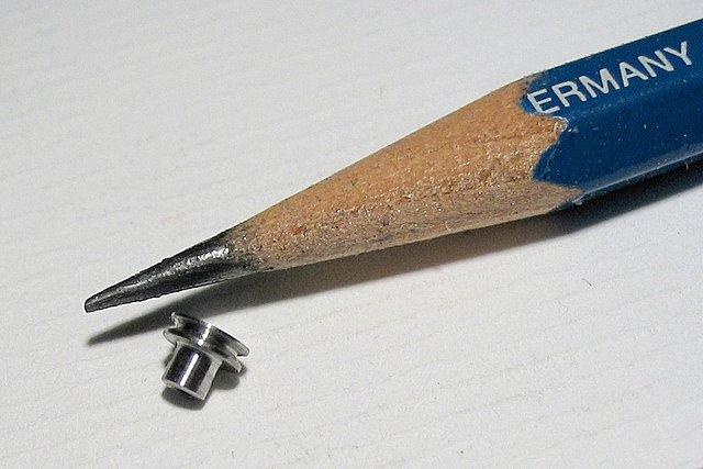
With no previous practice at machining under glass, I placed a piece of steel in the chuck and started the lathe. I was able to easily produce the miniscule V-groove pulley pictured below (an ordinary Staedtler 2H Pencil is used for reference).
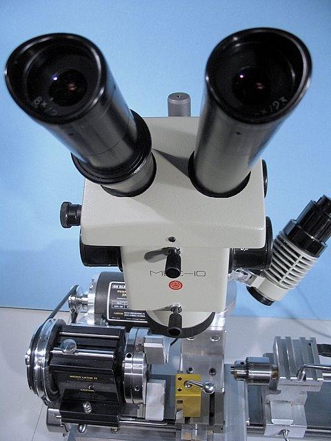
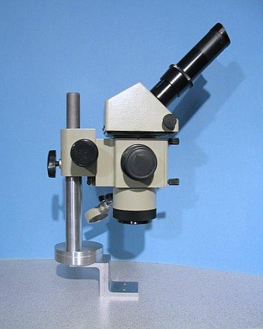
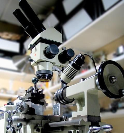
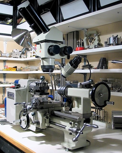
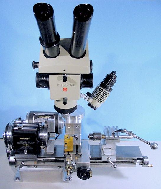
Lomo LF-100 / MBC-10 Stereo Microscope and the Taig 4500 Micro Lathe
An overall view of the microscope mount

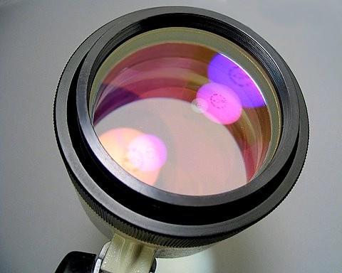
The bottom objective lens is a very large and somewhat costly piece of glass.
Logic would dictate that it requires protection from oil, metal dust and flying objects.
Objective Lens Bottom Element
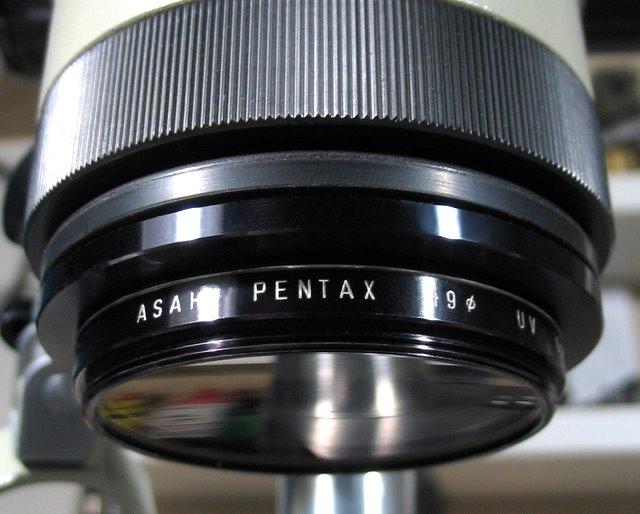
A common camera UV filter makes the basis for a nice protective cover.
A 49mm multi-coated curved Pentax filter

I mounted it convex-side-out for ease of cleaning, but also it can be quickly removed.
The raw components used to adapt the UV filter to the bottom of the objective
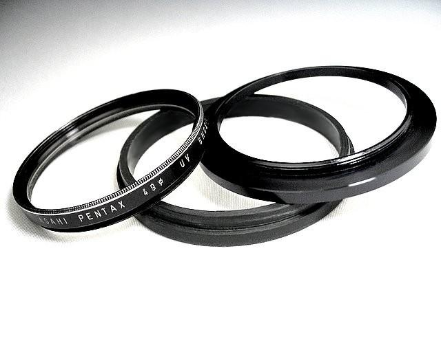
The ring to the right is a 58mm - 49mm commercially available filter adaptor.
The middle ring is made from a piece of PVC pipe that slips over the objective
nose and couples to the 58 mm side of the adaptor.
Complete Objective Filter
An objective view !
THE MOUNT
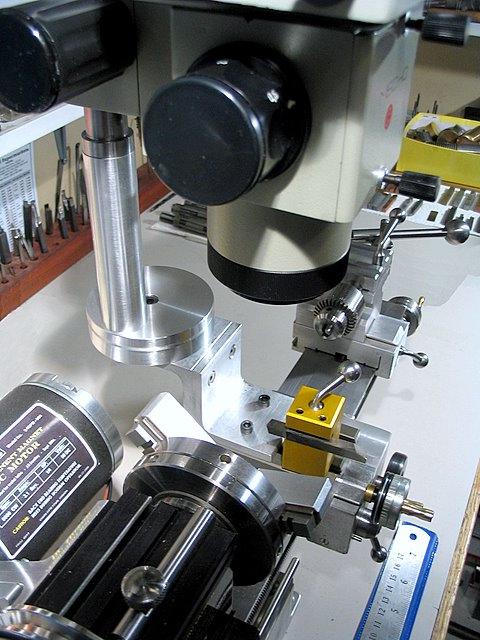
Before anyone gets too excited about any undue twisting forces imparted on the tiny cross slide by the weight of the microscope, have a look at this picture below.
Obviously all the weight is simply straight downward at the location of the foot.
The Taig slide can take this in stride - it is nothing compared to the normal
pressures which are encountered during many routine turning operations.
Motor clearance below the bracket
The flanged upper pole makes a swivel joint where it enters the base tube.
The upper steel pole was treated by a ferric chloride solution.
The entire unit swivels out of the way, giving a generous amount of access.

It will swing a full 360°
Well, well, well! ...it doesn't only fit the Taig!
No coincidence here...the adaptor was designed to eventually fit either of the lathes
Even the color matches
What can I screw the microscope to next?
- well there's still a Taig Mill on the end of the bench!
OPERATION:
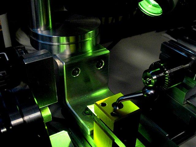
Rig for Green!
I have a separate white LED illuminator (not shown) - they can be swapped in seconds.
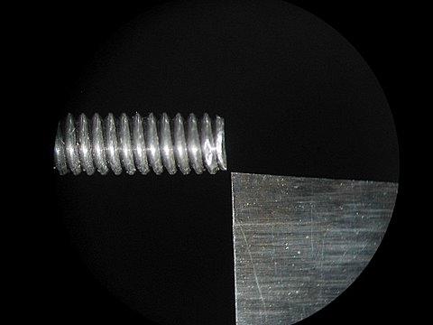
THE VIEW
OR
against a black background...
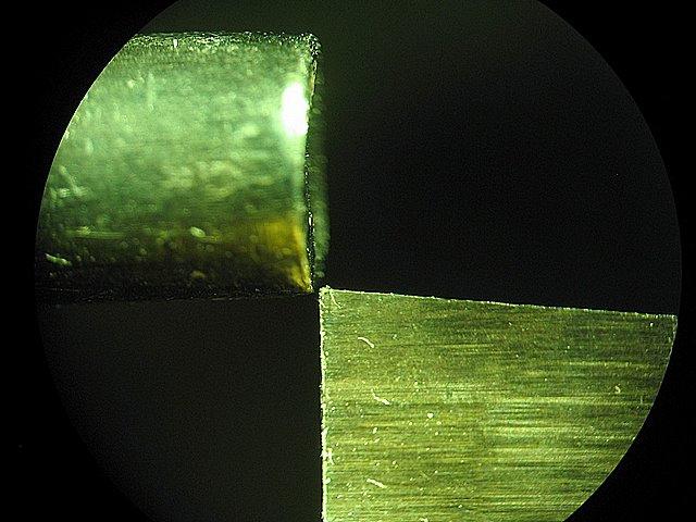
There is a lot to talk about in these two pictures above.
All of these pictures were taken with a 3.2 MP Canon A75 digital camera simply held up to the eyepiece. The focal length of the camera lens was such that the top and bottom portions of the circle were cut off. In some pictures on this page one side of the circumference is out of focus...this will be solved in future by ensuring the correct camera position with a proper camera-to-eyetube adaptor.
Since the microscope is fixed directly over the tool bit, the tool always appears stationary, even when being fed in toward the headstock. When turning, it appears that the workpiece is being fed into the tool like a piece of wood into a table saw blade.
At the lowest power (4.65x) almost all of the front surfaces of the 3" chuck's jaws are visible.
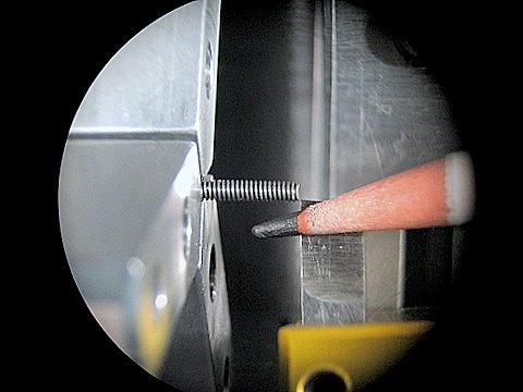
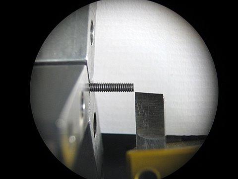
The threaded rod projecting from the chuck is UNC 2-56 tpi
What does a pin head look like?
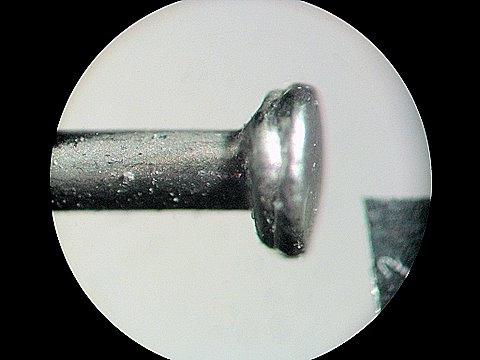
The last of those staged-backdrop pictures!
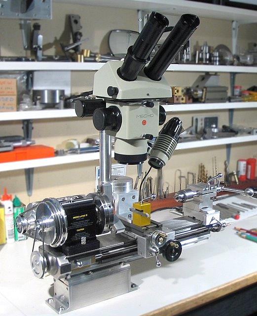
The Lomo and Taig make a powerful combination on the workbench
Will it work?
The same pulley mounted on a common household straight pin as a "shaft".
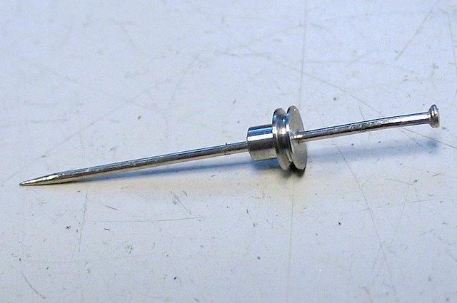
(no extra charge for the scratches on the countertop)
No keyway, but I'm fairly certain I could do it - but then who needs a 3/32" pulley anyway?
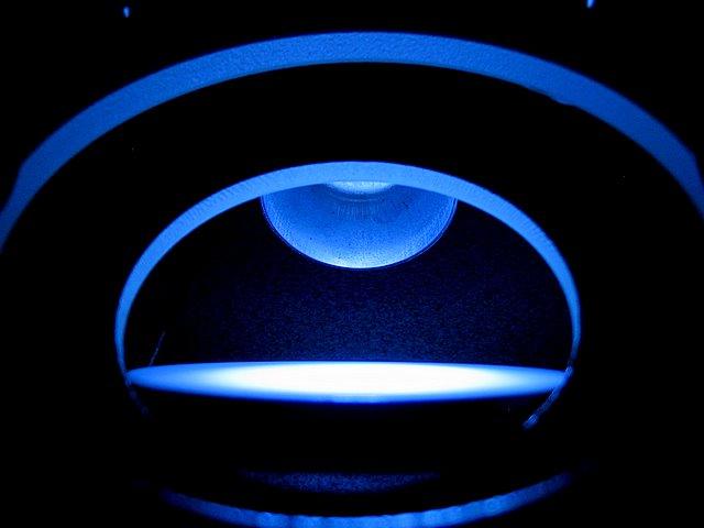
The parting shot - looking down into the MBC-10's diascopic base with diode illumination
The microscope home page gives a detailled description of this Lomo microscope, if you haven't visited it yet.
THE END (for now)
Microscope Home Page
Model Engines Workshop Page
Model Engines Home Page